1. Short Description
The current User Manual Tool presents the main functionalities of the
Service Continuity Module (SCM), which is a software application that allows
the operators of Ground Segments (GSs) to assess the operability of their
organization when it is subjected to a combination of cyber and/or physical
attacks. SCM was developed in Python in the context of Task 5.6, namely the
“Development of service continuity scenarios for cyber and/or physical attacks”
and is integrated in the ENGAGE platform to offer GS operators a Graphical User
Interface (GUI) for rapid assessment of real or hypothetical disaster
scenarios.
2. Main Purpose and Benefits
SCM was
developed to allow GS operators to assess the impact of various cyber and/or
physical attacks to their organizations in a quantitative and illustrative way.
It can be used during the development of comprehensive Business Continuity
Plans (BCPs), by realizing hypothetical disaster scenarios to help the users on
better understanding the critical components of their business and on developing
pre-defined response procedures to enhance business survivability. Moreover,
SCM may be used as a crisis management tool by feeding actual downtime data
during a real disaster event, allowing
GS managers to compare different mitigation actions and
ultimately helping them to select an optimal recovery strategy.
The
failure propagation algorithm that is supported by SCM is based on the Generic
Operational Model (GOM) approach, which involves the discretization of a
business into a series of critical physical/cyber Infrastructure Components
(ICs) that are interconnected to form the “supply chain” of the organization. GOM
is unique for a GS and it can be derived by expert elicitation methods, i.e.,
by the collaboration between (a) GS operators who fully understand the
operational workflow of their organization and (b) Business Continuity (BC)
experts who can assist the former to delineate the interconnections between the
critical components.
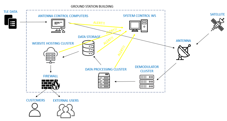
Figure 2‑1
illustrates an example of a GOM for a GS that receives satellite data via an
antenna, processes and stores them into data storage racks, and finally makes
them available to the external users and costumers using a website application.
Each node on the GOM graph corresponds to a unique critical IC, which may
consist of several (sub-)assets. For instance, if the GS employs three antennas
for the acquisition of satellite data, then the “Antenna” IC has three assets. More
details regarding the development of GOMs and the failure propagation
methodology can be found in Deliverable 5.6 of the 7SHIELD project.

Figure 2‑1 – Example of a Generic Operational Model (GOM) for a
GS
Each
of the critical ICs comprising the GOM of a GS are vulnerable to several
cyber/physical threats. For instance, disruptions in the “Antenna” IC of Figure 2‑1 are mostly related to
physical threats, such as power shutdowns, damages to the fibre cables or to the
structural system of the antenna.
On
the other hand, ICs such as the “Website cluster” can also be vulnerable to
cyber threats, like Distributed Denial-Of-Service (DDOS) or Man-In-The-Middle
(MITM) attacks. Thus, after the derivation of the GOM, the GS operators along
with the BC experts shall identify a list of potential threats for each
critical component, along with the corresponding expected downtimes needed for
the organization to fix the issues.
The construction of the GOM, the identification of the potential threats,
and the definition of the expected downtimes comprise the initial steps needed
to setup the SCM for a specific GS. These three steps are deemed to remain
unchanged when performing the service continuity scenarios using SCM, as they
require expert BC practitioners to capture the interdependence of essential
components and their impact to the operability of the business. Thus, while the
tool allows for modifications in the operational structure of the GS, it is
recommended that users do not make changes without the guidance of BC experts.
On the other hand, SCM offers the opportunity to the GS managers to rapidly evaluate
several hypothetical or actual disaster scenarios and to obtain intuitive graphical
results of the impact analyses for efficient comparison and assessment. To
support SCM users with the easy and rapid execution of such analyses, a GUI module
was developed by SATWAYS and integrated in the ENGAGE platform, which will be described
in the following sections.
3. Main Functions
There is
only one main function available in the SCM. The application receives as input two
files, one related to the operational structure of the GS (GOM, threats, etc.) and
another containing the disaster scenarios, i.e., the case studies to be tested.
Consequently, the failure propagation algorithm is performed for each case
study and a folder is created with images and GIFs related to the results of
each analysis. When using the GUI module, the definition of the case studies
and the display of the results are handled by the ENGAGE platform.
4. Integrations with other Tools
SCM can
be used as a standalone application, in which the user has to create the two
input files and then call the main function of the program. When using the GUI
module integrated in the ENGAGE platform, the user graphically selects the
threats and downtimes of each
component, while the input files and the call of SCM’s main function are
handled by ENGAGE. In this sense, ENGAGE mainly serves as a proxy to help users
on creating the input files needed by SCM and displaying the results.
5. Infrastructure Requirements
SCM was
developed in Python 3.9.7 and thus it is a cross-platform application that can
be run both locally and remotely. When using the GUI module of the ENGAGE
platform to visualize the service continuity scenarios, the infrastructure
requirements of SCM end up being those of ENGAGE, in which case the users are
advised to read the pertinent User Manual.
There are no specific performance requirements to run SCM, as in a
typical GS comprising few critical components with simple interconnections, the
failure propagation algorithm converges relatively fast. The main time
bottleneck of the software is related to the creation of the images and GIFs per
impact analysis; however, the users may decrease the number of timesteps for
which an image is created to effectively reduce the total runtime of the
analyses.
6. Operation Manual
6.1 Set-up
SCM is written in Python 3.9.7
programming language and uses several python libraries that are needed to be
installed locally. The required packages are given in the requirement.txt
file, which can be installed using pip installer:
pip install -r requirements.txt
When using the GUI module of the
ENGAGE platform, no set-up is required by the user.
6.2 Getting Started
After installing the required
packages, the application can be executed in standalone mode by calling the
main function:
python -main.py -i <inputdir> -o <outputdir>
Where <inputdir> is the
directory in which the input files reside and <outputdir> is the
directory used to save the analysis results (a new folder is created if the
directory does not exist).
When using the GUI module of the
ENGAGE platform, the user has to open the SCM tab, realize the disaster
scenario by selecting specific threats or downtimes per critical IC, and then click
on the “Finish” button to execute the scenario.
6.3 Nominal Operations
There are two input files needed by
SCM to run the service continuity analyses, which are written in .json format and reside in the folder <inputdir> given by the user. The first one
is the BusinessComponents.json, which contains all the data related to the operational model of
the GS, namely the GOM, the potential threats, and the expected downtimes. Each
critical IC comprising the GOM contains several attributes like ID, short name,
full name, and number of assets (Figure
6‑1(a)).
Specifically, the “NumAssets” attribute corresponds to the number of individual
assets composing an IC(e.g., if there are four antennas in the GS, the “NumAssets”
attribute of the “Antenna” component will be equal to 4). The file also
contains a list with the potential cyber/physical threats and a table with the
expected downtimes per component (Figure
6‑1(b)). As
explained before, this file is expected to be constructed by BC experts and
thus users should exercise caution when modifying it.
(a)
Figure
6‑1 – Example of BusinessComponents.json
input file, showing (a) the definition of critical components and (b) the
potential cyber/physical threats and expected downtimes.
6.3.3 User Inputs
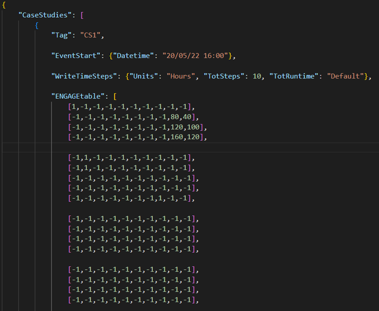
The second input file is the CaseStudies.json,
which contains a series of independent disaster scenarios (i.e., case studies)
requested by the user. Each case study has a specific tag name, time of occurrence,
and a matrix named ENGAGEtable containing the cyber/physical attacks per
asset. Figure 6‑2
illustrates an example of a case study by the name “CS1”, which occurred in
20/05/2022 at 16:00. A snapshot of the considered business model is shown in Figure 6‑1(a), in
which the first critical IC is the “Antenna” that comprises four assets. As a
result, the first four rows of the ENGAGEtable contain information for
these four assets. The next critical component is the “Demodulator cluster”
that consists of five assets, and thus the next five rows of the ENGAGEtable
are related to them, etc.
The first 8 columns of each row
correspond to the 8 potential threats that can impact the individual components
(Figure 6‑1(b)),
with 1 meaning that the asset was impacted by the specific threat and -1 that
it was not. For example, in the case study of Figure 6‑2 the
first antenna was impacted by the first threat, which corresponds to “Power
Supply Shutdown”. The next to last
column is used in cases where the user wants to directly set the downtime for a
specific asset (e.g., in Figure 6‑2 80 hours for the second antenna, 120 for the
third, 160 for the fourth). Finally, the last column is used for the “Business
Continuity” module, when the user wants to assess the effect of different
mitigation actions and compare them (e.g., how the loss of service will be
reduced if the second antenna shutdowns for 40 hours instead of 80, see Figure 6‑2).

Figure
6‑2 – Example of CaseStudies.json
input file.
When the GUI module of the ENGAGE platform
is used, the user can graphically select the several threats per asset by clicking
on the “Threat Configuration” tab and enabling the pertinent checkboxes, as
shown in Figure 6‑3. On
the other hand, by clicking on the “Downtime Configuration” tab (Figure 6‑4), the
user can directly setup the downtime per asset, in which case the selections in
the “Threat Configuration” tab are ignored for this specific asset. Like in the
.json files, the first column by the name “Downtime” is used to setup
the downtime per asset, while the second is used for the “Business Continuity”
module, in which different recovery scenarios are compared. Finally, when the
user clicks on the “Finish” button, a CaseStudies.json file is created
automatically by ENGAGE and SCM is executed.
Figure 6‑3 – Snapshot of the “Threat Configuration” tab in the
ENGAGE platform
Figure 6‑4 – Snapshot of the “Downtime Configuration” tab in the
ENGAGE platform
6.3.4. User output
When the user finishes with
configuring the disaster scenarios, SCM is called (automatically in the case of
the GUI module), and then the impact analyses are executed. For each scenario a
set of images and a GIF are created and saved in the <outputdir> directory
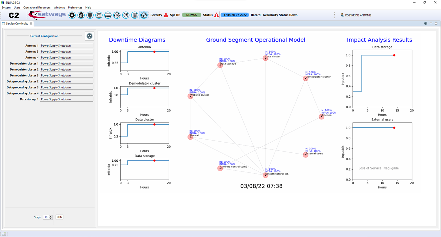
given by the user. These results are also displayed in the ENGAGE platform, as
shown in Figure 6‑5. The three
figures in the left of the screen show the downtime diagrams of the impacted ICs,
in this case study the “Antenna”, “Demodulator cluster”, and “Data cluster”
components. The graph in the middle of the screen illustrates the GOM and the
propagation of failure in the critical components of the organization, which
are measured by the InfraIdx and InputIdx indices (for more
details see Deliverable 5.6). Finally, the two figures in the right side are
related to the impact of the attacks to the functionality of the GS, using two
metrics: (a) the loss of satellite data and (b) the loss of service as
experienced by the external users. Moreover, a message is given in the screen
to warn the user if the loss of service is Negligible, Low, Moderate, or High,
in order to support his/her decisions.

Figure 6‑5 – Snapshot of the SCM results int the ENGAGE platform